Table of Contents
TeleRouter user manual

Art.Nr. 9373-ANALOG
Art.Nr. 9373-ISDN
Art.Nr. 9373-PPPOE
![]()
1 Description
For remote maintenance via the analog or ISDN network select at TELE-Router spot a Take TELERouter as a secure VPN gateway between the automation network and the corporate network, connect the network nodes via the 4 switched network ports routes between two networks using the WAN ports the TELE-router holds as an NTP server S7 Time is always up to date ProfiNet also supported
!Attention!
At the analog or ISDN jack ONLY must the device type according to a cable are plugged! Nevertheless, if a non-device type appropriate cable plugged in, it can lead to damage at Hardware . The device type identified by the ticked box and the label on the sleeve.
2 Installation
2.1 Power connection
For the power supply to the device is either the included AC adapter or an existing local power supply with min. 24V DC 350mA power connected to the 3-pin green plug. In the included AC plug adapter the power poles are marked with colored sleeves.
The PLUS-pole with the color “red”, the MINUS pole with the color “blue”. Connect the POSITIVE pole of the left screw terminal and the NEGATIVE pole on the right (outer) screw terminal. The middle connector is used to ground and must be connected to PE.
2.2 LAN-connector
This connector is an autosensing 10/100 Mbit/s connector. For the connection to a Hub or a network connector, you should use a socalled patch-cable (both sided RJ-45, 1to1, shielded).
2.3 Analogue-modem connector
When connecting the telephone, the cable with the black (TAE-)plug is plugged in the telephone socket (N-contact). Please note that with some plugs a locking device has to be removed with a screwdriver in order to extract the plug from the TAE-socket. The other side, a so-called western-plug, has to be plugged, with the ejector up, in the small hole of the modem. You will hear how the locking device latches. In order to extract the western-plug, simply press down the locking lug and extract the plug.
3 Introduction
TeleRouter is a scalable router with 4 x LAN - switch port and 1 x WAN port. Optionally can be installed an analog or ISDN modem
Via the integrated web interface, you can configure and operate TeleRouter. Applications for TeleRouter are e.g. Gateway / Connect / remote maintenance of
automation networks profinet networks or standard Ethernet networks
Especially TeleRouter supports Simatic S7 systems from Siemens. With a few simple steps TeleRouter is ready for the desired mode. The optional analog or ISDN modem also enables operation as a dial-up (dial-in) router. For TeleRouter are available extension modules depending on the mode.

4 Hardware performance
4.1 Standard hardware performance
In the standard version TeleRouter is configured with a WAN port and 4 LAN ports equipped as a switch. The following operating modes are possible.

4.2 Modem upgrade
Equipped with a modem (analog or ISDN), in addition to the standard features the TELE-ROUTER can be used as dial (dial-in) router. .

4.3 Configuration

In the configuration can be set the network, routing mode, etc. The data entry forms are self-explanatory as a rule. We are glad to accept suggestions from users to make operation even easier.
4.3.1 System button, Reset system
Under the item System button, you have two options which are allowed when the button is pressed, at least one option must be selected:

| allow factory settings |  | The device can be set to the delivery condition |
|---|---|---|
| Allow start by default | | The device is set to the already stored basic settings |
Attention!
Use one of the 4 switch ports to configure it because it may happen that the WAN port is no longer accessible
Do not leave the unit in operation. Disconnect the device from the production network and perform the reset in an autarkic environment. The configuration computer and the device should
While not connected to the company network
No worries we do not take any work rest.
The button hides between WAN and LAN ports (small hole). Only the activated options are available.
Proceed as follows:
- E.g. Office clamps
- Make the device de-energized!
- Insert the clasp in the hole
- turn back on
- When the four LED's go out and only the power LED is on, hold down the button with the office clip until all four LEDs flash fast
- Release the button
- Now appears a sort of selection. When the button is pressed in the desired state, the desired action is performed
- Basic setting
- LED S3 (bottom right) flashes
- The device boots in the basic setting (network / IP addresses of the delivery state are used). Now you can make the desired changes to the network settings. However, these settings are not activated until the device is restarted.
- Factory setting
- LED Power and S3 flash
- All settings are deleted
4.3.2 Settings

| parameter | possible setting | routing direction / purpose |
|---|---|---|
| device name | “as desired“ | |
| ProfiNet | yes /no | determines whether the TeleRouter as ProfiNet routers are used, define you as a routing interface: WAN / OVPN |
| standard gateway | fixed (as specified) WAN viaDHCP WAN via PPPoE LAN via DHCP Modem via PPP | |
| 1. DNS | ||
| 2. DNS | ||
| routing mode | office | LAN → routing interface |
| machine | routing interface → LAN | |
| routing interface | WAN/IP | IP routing via WAN |
| modem | IP routing via Modem | |
| WAN/PPPOE | IP routing via PPPoE at the WAN port | |
| WAN/OVPN | routing via OVPN at the WAN port | |
| WAN/bridge | Ethernet routing at the WAN port |
4.4 ProfiNET router (only possible with ProfiNET option)
If ProfiNet is enabled the TeleRouter is used to connect / remote maintenance of Profinet networks. Here is a schematic example.


The Profinet connection is implemented via a secure VPN connection. VPN connection can be established via WAN (TCP / IP) or WAN / PPPoE. To set a Profinet connection with 2 x message router: When ProfiNet is activated, telephone routers used to connect / remote maintenance of Profinet networks. Here is a schematic example.
- Activate ProfiNet option on both devices.
- Setting up a page as OpenVPN server and the other as OpenVPN client (see below)
- Possibly activate DynDNS / PPPoE
The devices will connect automatically. Upon successful connection between the two can Profinet networks to communicate.
Attention!
It is no real-time data exchange possible.
| Parameter | Possible setting | routing direction/ purpose |
|---|---|---|
| name of device | “as desired” | |
| ProfiNet | yes /no | determines whether the TeleRouter is used as ProfiNet router Do set its routing interface: fix WAN / OVPN |
| standard gateway | fixed (as specified) of WAN via DHCP of WAN via PPPoE of LAN via DHCP of modem via PPP | |
| 1. DNS | ||
| 2. DNS | ||
| routing mode | office | LAN → routing interface |
| machine | routing interface → LAN | |
| routing interface | WAN/IP | IP routing via WAN |
| modem | IP-Routing via modem | |
| WAN/PPPOE | IP routing via PPPoE at the WAN-port | |
| WAN/OVPN | routing via OVPN at the WAN port | |
| WAN/Bridge | ethernet routing at the WAN port |
4.5 WAN-settings / LAN-settings

The WAN / LAN port can each receive up to 3 different IP addresses and subnets.
The port can also be used as a DHCP server or client. Here are entered the necessary data for the IP assignment.
For the operations of a DHCP / Server can be set fixed assignments MAC-IP-adress.
(See below, “DHCP fixed addresses). Next is to define which services are available at the port (web config), ping, ssh (only for developers)
4.6 Modem settings

Here the modem parameters are defined. A modem connection is realized as a PPP connection. This allows also be used with TeleRouter alia dial routers. An ideal replacement for example is TeleService IE from Siemens. In the bottom line can be determined which services are available at the interface.
| Parameter | Possible setting | Purpose |
|---|---|---|
| Type | auto GPRS/UMTS | Sets the modem type, auto = ISDN or analog |
| Port | on board LAN | Connecting the modem |
| LAN TCP/IP-Port | IP-Port of the LAN-Modems | Only for LAN modem |
| LAN IP-Adr | IP address of the WLAN modem | Only for LAN modem |
| SIM-Pin | Pin of the SIM card | Only for GPRS / UMTS Enter the SIM-pin before connecting the modem, otherwise the SIM-card could fall into the PUK-state by sending an incorrect pin |
| Dial-up mode | Ton Impulse | Sets the election procedure. Sound or pulse. Standard is sound, only old telephone systems require impulse. |
| Substation | Yes No | Indicates whether the operation is on a PBX. If yes, the exchange should be stopped |
| Number of rings | 0 - 5 | Number of rings before the modem receives a call 0 = modem does not cancel |
| Country | Select the country in which the device is operated | The modem adapts to the technical characteristics of the telephone line in the respective country. As a rule, a choice is available between Europe / Germany and the USA |
| max Baudrate \\(Only analog modem) | Maximum connection speed that the modem uses. | With varying line quality, it may be more effective to operate the modem at a lower speed. This saves automatic negotiation of new modulation. |
| MSN/EAZ | (only ISDN) Device number | This is used to determine the terminal number that the ISDN modem responds to when calling. No input means the modem is always responding. You can call this number from your telephone provider or telephone system administrator |
4.6.1 Using the LAN modem
As of version 1.65, the GPRS LAN modem LAN HT is supported.
Please note the following:
- Connect the modem directly, to LAN or LAN port. For a LAN connection to be guaranteed
- Enter the corresponding parameters for port and IP addresses
- Enter the SIM-pin before connecting the modem, otherwise the SIM-card could fall into the PUK-state by sending an incorrect pin
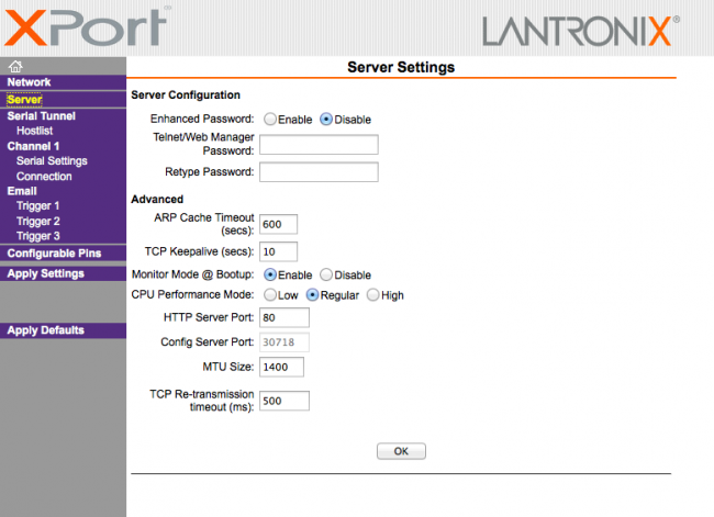
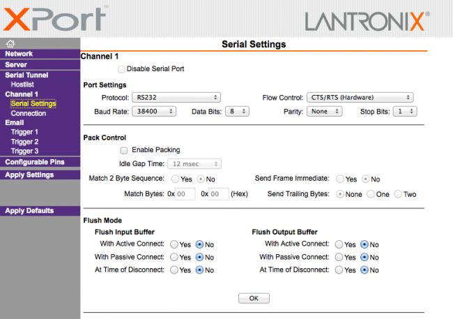
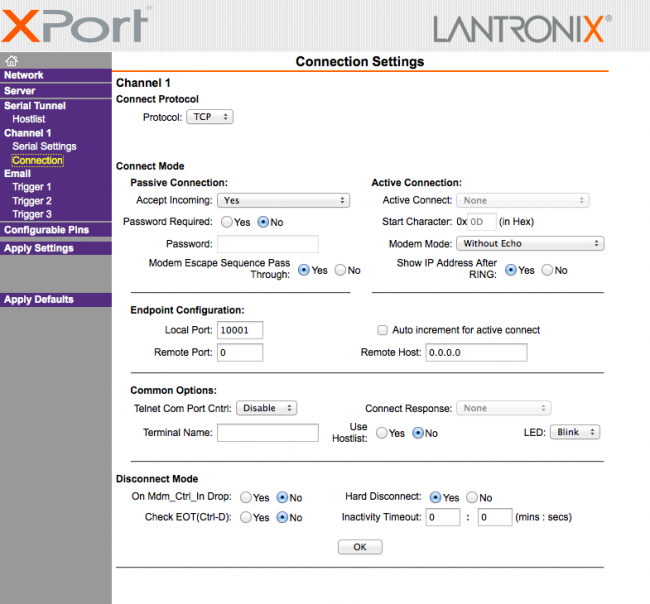
Settings on LAN Modem. The following pictures show the settings of the LAN modem.
Use the modem's built-in WEB browser.
Important:
- Set KeepAlive to max 10 seconds
- Disable Telnet Cntrl
- Remote Port = 0
- IP address and port as configured in the TeleRouter
The connection status of the LAN modem is displayed in the system status:
- TCP / IP connection
- Logged-in network (e.g., T-Mobile)
- Signal level
4.7 PPPOE settings

Define here the parameters for operation at a fixed DSL / cable modem. To overview and easier configuration are possible also the default gateway and DNS settings. As a rule, here are to set “auto PPPoE”.
Here can also be selected which services are available at the interface.
| Parameter | possible setting | Purpose |
|---|---|---|
| PPPoE at the WAN | yes no | Determines whether the PPPoE WAN port should be active. |
| PPPoE-name of service | optional | is provided by your ISP. Usually free |
| user name | as submitted by the provider | |
| password | as submitted by the provider |
4.8 Phone book

| Parameter | Possible setting | Purpose |
|---|---|---|
| name | name of the entry | as desired |
| phone number | number of the user | By clicking on the number, the connection established |
| baud rate (not at ISDN) | 1200- 56kBit | maximum connection speed with the partners |
| user | user from the user list | For the dial-up user access is be managed dial-up user managed |
In the phone book are managed all facilities with a modem connection. The connection with a partner is simply done by clicking on the phone number. User and password are maintained in the dial-in user database. Thus it possible to use a multi-user systems. TeleRouter can also be used for other dial-up PPP access.
4.9 Routing firewall rules

Normally the routing is allowed on all network subscribers. As soon as there is an entry in this table, an access will be possible only via the rules above. In the standard edition the routing is only possible for LAN or from LAN. See operating mode. The “operation of the Advanced” allows rules in both directions.
4.10 DynDNS Konfig

If TeleRouter to be reached by OpenVPN as via the Internet, the Internet IP address of the device must be known. Meaningful here is not to work with a fixed IP address because the provider possibly allocate a new IP address here after new connection establishment (eg via PPPoE). It makes more sense here to access the device always with the same domain name.
The service provider DynDNS offers this service on the Internet. (http://www.dyndns.org). DynDNS = Dynamic DomainNameSever. For operating the service, you must sign in to DynDNS. For more information visit the website of DynDNS. Up to 5 dynamic IP adresses are free. If you need several, you can book at DynDNS for a fee a corresponding number of domain names. The price is very low, about 30, - U.S. $ per year.
Roughly speaking, this means:
You register at DynDNS the desired host name. e.g. meineanlage.dynalias.com. For your access you will receive an username and password. Enter this data in the setting of a DynDNS config and set “use DynDNS” to yes. The DynDNS refreshes in the selected time interval the data in DynDNS. If the Provider assign a new IP address that will be corrected again within this interval, thanks DynDNS. You reach your TeleRouter under the registered name, eg: meineanlage.dynalias.com.
Enter this domain name in your office device at the VPN users.
| parameter | possible setting | purpose |
|---|---|---|
| name | any desired text | serves for info |
| protocol | TCP UDP TCP/UDP ARP | The protocol which is to be routed |
| port | 1 - 65565 | port or port area, which is to be routed z.B 1 – 1024, 2002 – 2048, 8080, 0 means all ports |
| IP address | IP |
4.11 DHCP fixed MAC /IP address mapping

If the built-in DHCP server (at the WAN or LAN) is operated, it can be useful, to allocate specific IP stations always the same IP address. Here you can specify which MAC address is replaced by which IP address.
4.12 NTP client

So that TeleRouter always runs with current time, we have implemented an NTP client. This allows TeleRouter automatically synchronize over the Internet or by any other available in the network time server date and time.
| Parameter | Possible setting | Purpose |
|---|---|---|
| NTP client mode | yes \ no | switch NTP client on or off |
| name of service | IP adress / domain name of the NTP Server | Enter the IP address or the domain name of the desired NTP server. Be sure that this Server via the specified routed away accessible. |
| time zone | timezone in which the TeleRouter operated | necessary so TeleRouter has the correct local time |
4.13 Open VPN settings

In TeleRouter we have implemented the popular OpenVPN released under open source.
Detailed information can be found at http://www.openvpn.net.
Here I would like to briefly explain the function of OpenVPN, as implemented in TeleRouter.
Basically there are two modes of the OpenVPN: Server or client.
A server normally configures the device to the system (machine).
With OpenVPN we present TeleRouter in a new network interface. This interface is connected via a line (virtual circuit) with the OpenVPN interface of the partner device. The line is implemented by software. Here are exchanged all protocols for this interface on its own UPD / TCP channel. One can say it is made a telephone connection between the devices via UDP / TCP. Of course, the connection is encrypted. The keys are stored in the message router.
Configuration OVPN operation:

| parameter | possible setting | purpose |
|---|---|---|
| OVPN mode | no OVPN server (UDP) client (UDP) server (TCP) client (UDP) | sets the OVPN operating mode of the device. In the server mode TeleRouter waits for a connection, In the client operating TeleRouter takes even before the connection to the partner. |
| port | 1024 - 65535 | port number on which the OVPN service will run, standard 1194. |
| IP pool (only for server) | default: 10.111.111.0 | out this pool, the partner (client) will be allocated the IP address. |
| IP pool netmask | default: 255.255.255.0 | associated netmask for the IP pool |
| server adress (only in client operating) | IP adresse or URL of the servers | the address of the server. Can take place in the notation xxx.xxx.xxx.xxx or in plain text (as a URL). Is only used in client mode. |
| user | user name | name of the user with which the server will be logged |
| password | user password |
The options “services on the interface” determine what services are available at present VPN connection.
Open VPN routing
This determines, in what form should be routed to the WAN / LAN port via VPN.

from: Routing is not possible to interface
===>: Routing from the VPN interface
⇐==: Routing from the Interface to the VPN
⇐=⇒: Routing in both directions
admission
Who is now allowed to build an OpenVPN connection? How can access to be controlled?
CAUTION! In principle, each of the certificate and the IP address of the TeleProf has
and establish a VPN connection to access the device. It is to compare when you connect
the device to the telephone line and assign a password for the dial-up modem.
You can use the extension “Advanced Router” for your own certificates. This provides more security.
4.14 VPN user

Here you can manage the users who are allowed to connect via OVPN.
4.15 VPN connections

In the VPN connections which are similar to a phonebook to manage your machine. If the time server address, protocol and port are entered, it will enter a reference to a VPN user (see previous).
4.16 VPN-user
Here you can manage the users who are allowed to connect via OVPN.
4.17 VPN-connections
In the VPN connections may be similar to a phonebook machines to be managed. It becomes server address, protocol and port is entered. It will be a reference to a VPN user entered.
4.18 User management

In the user management you manage the users, with what right the WEB interface is allowed to be operated.
Moreover, the access data for user to be maintained, which is a dial-up connection (modem).
4.19 WEB-User
Here is the mask for entering the web interface user. Per users can be assigned various permissions. Generally, only a user with “SU” is allowed to make changes. U1 - U5 may only use the interface. In TeleRouter expansion modules have “U1” - “U5” more precisely specified servicing rights.

4.20 DFU Users
Here is the mask for entering the dial-up user interface. The user receives only the access when active is on “yes”. Further is only available the addition of “dial in & out” or “dial out”.
When a user dials in, all entries are reviewed to “dial in & out”. Other users are denied the access. The assignment take place in the phone book.

4.21 System status
Display the device status

5 Optional functions
5.1 HMI message module

With the HMI message module, SMS and email messages (fault messages and maintenance messages) can be sent automatically to virtually any number of recipients, depending on the event, in the PLC, without any programming effort. The system automatically assigns the messages to the respective recipients and sends the message via the correct provider.
Please note:
By sending SMS messages and email messages arise
Additional costs (telephone charges, charges for Internet access, etc.). Please check with your provider for the amount of the respective fees.
For the HMI module to work properly, some basic settings must be made.
The following items must be set up:
- Pagerprovider
- Pager receivers
- Emailserver
- Email recipient
- PLC connections
- PLC Varials
- Standardization (optional)
- Notifications
- Initial setting Activate the HMI option
- Activate SMS dispatch or activate email delivery
The HMI module is also secured by access protection via WEB browser. The necessary rights are indicated for the corresponding points.
Setting up the email server or email account

In order for the TeleRouter to send an email, we need an email account or a server that receives and forwards the messages.
Under Name, enter a meaningful expression for you.
The “Address” field contains the host address of the e-mail server. You can either use a local server (on the local network) or a public on the Internet. The input can be a name (for example, mail.gmx.de) or a fixed IP address.
However, ensure that the corresponding entries are set for the DNS server, gateway or routes, in order to ensure a smooth e-mail transmission.
If an email is sent for shipping, TeleRouter first attempts to reach the appropriate server via the current options (set DNS and gateway).
If this is not the case, an Internet connection is established under the setting Configuration → PPPoE / DSL or Configuration view → Internet → Provider and then tries to find the server. This connection is also used when the Internet connection is set to manual. If the connection to the Internet was established,
This is separated after 2 minutes of idle (no email is present) or after 10 minutes at the latest.
For the Internet via modem, you can use so-called Internet by Call providers.
ATTENTION: Additional costs arise. Please inform yourself.
Example: Arcor InternetbyCall: Phone number: 01920793, User: arcor Password: internet (analog and ISDN)
In the “Email message buffer” menu item, you can track the status of the email and find any errors.
'Email' is the mail address that the recipient sees as the sender. This address should be as far as possible, as otherwise anti-spam filters might eliminate these messages. User and password refer to the email account.
Setting up email recipients

In the next step, you define the recipients of the e-mail messages.
| Field | Description |
|---|---|
| Name | selectable display name |
| address of the recipient | |
| Server | select the desired email server for sending to this recipient |
| G0 - G9 | Message Groups. Each recipient can not belong to one or more message groups. Below, you can assign different message groups for each message, similar to this one. Thus, a message can be distributed easily to the relevant recipients. |
Create message
Connections are required to access the PLC. Connections are currently supported for the SIMATIC S7 over TCP / IP.
Then configure the desired variables.
You can now specify scaling for output.
Then, you create your desired messages.
Configuring PLC connections

| Field | Description |
|---|---|
| Name | own name of the PLC |
| Connection | connection type to the PLC (here TCP / IP) |
| active | Communication with PLC |
| Cycle | defines the time period according to which the PLC is to exchange data |
| Adr. SMS status | is intended for feedback of the status of the HMI module. If you want to monitor the communication status and the SMS dispatch in the PLC, enter the address of a “word on” there. E.g. Data block or flag. TeleRouter then writes the maximum number of send attempts for pending messages for each communication cycle in the low-order byte. If the number exceeds 254, 254 is always used here. The background for this procedure is explained later. If the number of send attempts is> 0, the sending of a message has failed. This allows the PLC to monitor the SMS dispatch. Now, you should also monitor whether TeleRouter is communicating with the PLC. This can be done easily. Describe the counter byte in your PLC regularly with 0xFF. After the specified cycle time, a value other than 0xff must be set there. However, you should measure this time generously as the cycle can shift if communication problems occur with other controllers. The high-order byte is reserved for later extensions. This is currently overwritten with “0”. Example: If you are using MW 200, the MB201 has the counter reading and in MB200 the value is 0 |
Configuring variables

Now create the desired variables to be displayed or processed.
| Column | Usage | ||||
|---|---|---|---|---|---|
| Name | Name for free use | ||||
| Connection | you assign the variable of a PLC connection to | ||||
| Address | the actual address in the PLC according to the following rules: | ||||
| Data area | Data type | ||||
| Input | Output | Flag | Data block | ||
| E 1.0, I 1.0 | A 1.0, Q 1.0 | M10.1 | DB1.DBX 1.0 | Bit (Boolean) | |
| EB 1, IB 1 | AB 4, QB 4 | MB 20 | DB2.DBB 20 | BYTE | |
| EW 4, IW 4 | AW 6, QW 6 | MW 100 | DB4.DBW 0 | WORD | |
| ED 4, ID 4 | AD 6, QD 6 | MD 100 | DB4.DBD 10 | DWORD | |
| Timer | Counter | ||||
| T1 | —— | Timer | |||
| —– | Z1, C1 | Counter | |||
| Data type | Select the data type for the correct conversion: Boolean (bit) unsigned int (signed-to-unsigned) signed int (signed-byte) DWORD (double-word without sign) signed DWORD ) real (flow point number) |
||||
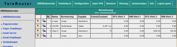
For correct display and processing of the variables, a conversion may have to be carried out. This conversion can be done with standardization. You can define the necessary conversions here and assign them later to the messages. Since standardization is usually more common, it is useful to manage it centrally.
| Column | Description | |
|---|---|---|
| Name | freely forbidden name | |
| Normalisation | Normally, two normalization modes are supported, either “linear” or “text”. linear means that the value must be converted by the PLC. In this case, the fields “PLC value1”, “HMI value1”, “PLC value2”, “HMI value2” are to be filled. Texts means you want the values from the PLC status texts assign. This may be e.g. The state of a multi-stage drive |
|
| Unit / State | For standardization “linear”, the text for the unit designation is shown here (For example, ° C,%, piece …) For standardization “Texts”, the states are listed here according to the following syntax: <Comparison> <value >: <Text> For each state, enter a new line. <comparison> is optional. If <comparison> is not specified, this means checking equality. Example for drive: 0: OFF 1: Level1 2: Level2 For comparisons, you can also define the following states: A temperature is to be monitored. It is to output only a text, whether the value is in the limit or whether a border violation is present. The value is in the limit if it is between 20 and 30. This is as follows: > = 20: normal ⇐ 30: normal <20: too low > 30: too high > 60: much too high Enter the number here as the number Values that result from the conversion of the fields “PLC value1”, “HMI value 1”, “PLC value 2”, “HMI value 2” |
|
| Conversion | For the conversion of the numerical value of the PLC for the representation as a physical variable in the HMI module, an assignment of the PLC value and the HMI value is necessary. The displayed value is calculated as: w = m * x + t; w = the displayed value m = (HMI value2 - HMIWert1) / (PLC value2 - PLCWert1) t = (HMI value1 - m * PLC value1) x = the current PLC value for example, the PLC values 0 - 1000 should correspond to the display 0 to 100 (sh line 3 in the picture) |
|
| PLC value 1 | PLC value that corresponds to the HMI value1. (0) | |
| HMI value 1 | HMI value that corresponds to the PLC value1 (0) | |
| PLC value 2 | PLC value corresponding to the HMI value2 (1000) | |
| HMI value 2 | HMI value corresponding to PLC value2 (100) | |
Configure messages
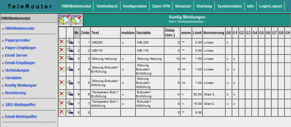
The actual messages are configured separately. The relationship between the variable, the standardization and the reporting group is made. What the actual message is. The sequence of the messages is made after entering the line number.
| Column | Use |
|---|---|
| Row | For the free use and information of the user / plant operator |
| Report | process the line and forward to message group (s) |
| Variable | Here you can assign one of the configured variables to the message. If no variable is assigned, only the text is displayed |
| Delay | The time in seconds for which an infringement must be applied at least until it is reported. Thus, a measured value can be debounced. If the condition / comparison operation is used to determine a limit value violation or to determine the reporting conditions. Possible comparisons: == , > = , ⇐ , <> and * * means no limit monitoring, thus only representation |
| G0 - G9 | The assignment to the individual message groups, the respective message is assigned to a group of recipients |
To activate the message processing at all, basic settings must be made. Before you activate these settings, the mediations should be projected.
The meaning of each line:
| Line | Use |
|---|---|
| Attachment name | This text is sent to the recipient in the SMS header so that the sender can identify the sender |
| Sending the send time | If “yes”, the send time is entered in the SMS header, Important: Set the time correctly |
| Enter message time | At “yes”, the time at which the message occurred was entered for each message. This makes the SMS / Email text longer and more extensive. However, the date of occurrence can be compiled for each message |
| Activate SMS server | yes / no |
| Max. Number of transmission attempts SMS | This allows the number of maximum transmission attempts per SMS recipient to be set. Thus, it is possible to minimize excessive costs for unsuccessful text messages in case of shipping problems |
| SMS sender identification for UCP | For the UCP protocol, the sender's telephone number must be given to the SMS server |
| Enable Email Service | yes / no |
| Max. Number of sending attempts | This allows the number of maximum send attempts per e-mail recipient to be specified |
SMS message buffer / Email message buffer

On the SMS Message Buffer page, the messages that are currently pending and not yet sent are displayed. The “Tx Trials” column shows the number of attempts already made to send the SMS. This is greater than 0, e.g. Telephone line not available, busy or service settings (telephone number) are not correct. The largest number of attempts is reported to the PLC (see above).
Clicking on the symbol ![]() deletes all messages in the list. The messages are not sent!
deletes all messages in the list. The messages are not sent!
For test purposes you remove the telephone cable, you can test the function of the system first, without generating costs for sending SMS.
View messages

In the menu item View messages you can view the current status of the messages. All message states of the configured messages are displayed there. So also these, which can not generate SMS. As a result, a state can be obtained via the system without PLC programming software. The message window is updated every 3 seconds. Red fields indicate that there is a violation of the limit value. Google Übersetzer für Unternehmen:Translator ToolkitWebsite-Übersetzer
6 Technical data
6.1 pin assignment power supply

Pin number Short form Designation Direction 1 P24V 24V DC voltage input 2 PE earthing input 3 M24V mass input
6.2 Pinning Ethernet
| Pin no. | Short name | Notation | Direction |
|---|---|---|---|
| 1 | TX + | receive line + | Out + |
| 2 | TX – | receive line – | Out - |
| 3 | RX + | send line + | In + |
| 6 | RX – | send line – | In - |
6.3 Pin assignment RJ12
| Pin number | Short form | Designation |
|---|---|---|
| 1 | NC | not connected |
| 2 | NC | not connected |
| 3 | A | A-line |
| 4 | B | B-line |
| 5 | NC | not connected |
| 6 | NC | not connected |
6.4 pin assignment ISDN
| Pin no. | Short Form | Name | Direction |
|---|---|---|---|
| 1 | NC | Not connected | |
| 2 | NC | Not connected | |
| 3 | TX + | Send line + | Out + |
| 4 | RX + | received line + | In + |
| 5 | RX – | received line – | In - |
| 6 | TX – | Send line – | Out - |
| 7 | NC | Not connected | |
| 8 | NC | Not connected |
6.5 Special Assignment ISDN socket
for the RS232 Device Type
| Pin no. | Short form | Name | Direction |
|---|---|---|---|
| 1 | CTS | Clear to send | Input |
| 2 | DSR | transmission device ready | Input |
| 3 | RxD | Receiving line input | |
| 4 | GND | Signal ground | |
| 5 | DCD | receive line signal detect | Input |
| 6 | TxD | transmission line | Output |
| 7 | DTR | Data device ready starting | |
| 8 | RTS | Request | Output |