Table of Contents
OPCmanager
![]()
Technical specifications
- Powerful and compact server with the OPC interfaces 1.x, 2.x and 3.x
- Complete support of current OPC specifications, such as OPC Data Access and OPC XML Data Access
- Unlimited number of connections
- Unlimited number of items
- OPCmanager projects are stored in XML format
- Real-time display of the protocol process
- Each configured control can be switched to the simulation mode, so that the external control can be dispensed with as real hardware. Since the visualization Victory, the visualfactory accesses the same control drivers as the OPCmanager, it can be used as a simulation environment.
- The connection of an item takes place in text form directly in the item table or via import of symbol tables. The format adjustment permits a type-specific processing.
- The reading intervals for each individual item can be specified ms-exactly.
- In run mode, you can switch to the item list at any time, thus reading the current setpoint and actual values, including their time stamps, as well as the status of the modules. With the help of animated symbols, the overall state of the communication can be recorded at a glance.
- Currently, the following protocols are supported:
- S7 TCP/IP (RFC1006, CP343-1, CP443-1, S7-LAN)
- S7 MPI / PPI
- S5 TCP/IP – H1 (RFC1006, CP143-TCP, S5-LAN, VIPA-CP)
- S5 AS512 (RK511)
- S5 3964R (RK512)
- Moeller PS4/PS416
- AEG A120/A250 (KS-Funktionen)
- Modbus RTU/ASCII seriell, TCP/IP, DFÜ
- IBH softec SoftPLC
- WAGO Ethernet TCP/IP FPC
- SAIA PLC (S-Comm)
- Mitsubishi FX/FXN/A -Serie
- Bosch BUEP19/19E seriell
- Bosch BUEP19/19E TCP/IP
Create new project
To create a new project, click the New button on the OPCmanager toolbar or select File→ New from the menu.
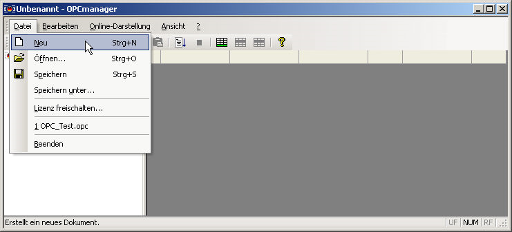
The project files of the OPC manager have .OPC as file extensions.
The project files are stored in transparent XML format. Since XML data is stored in the text format, it is possible at any time for external programs to generate project files for the OPCmanager.
Add control
To add a control, select the menu command Edit→ Add Control.
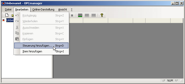
In response, the Add Controller dialog appears.
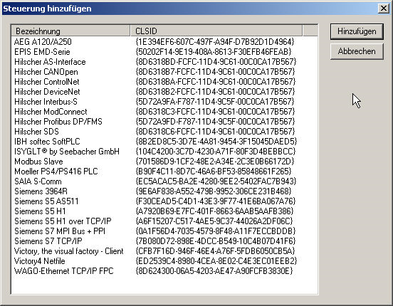
The list contains all currently installed communication drivers of the OPCmanager. Select the desired control and then click on it, this dialog closes.
Subsequently, the control's properties dialog is opened independently.
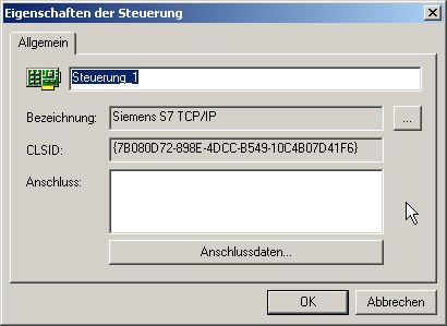
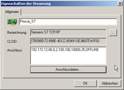
The automatically generated name of the control is overwritten with a meaningful description. Keep in mind that this name is used as a group name in the OPC syntax of the items, Press_S7.Druck.
The connection parameters of the control are entered in the text field connection. However, it is recommended to enter this data in the connection data dialog, since this data is adapted for each control.
In the case of Siemens S7 TCP / IP communication, the following dialog appears.
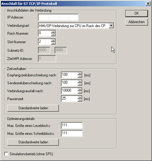
Fill out the necessary fields and then click on the OK button, then your settings are automatically transferred to the connection field of the properties dialog.
If you now press the OK button, the control has been successfully created.

Add OPC Item
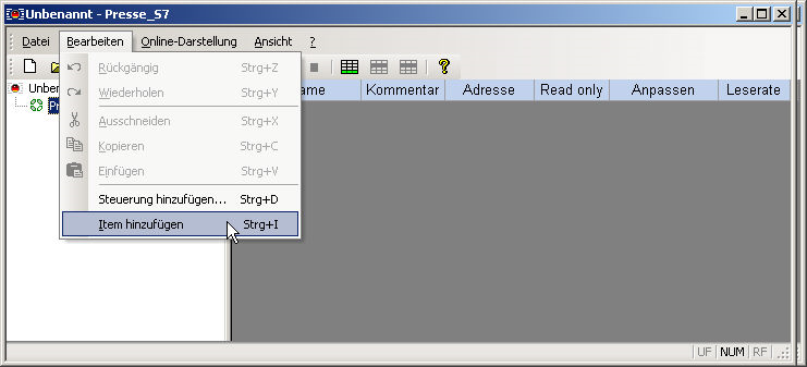
To create a new item, click the action button  in the toolbar of the OPCmanager or select Edit→ Add Item.
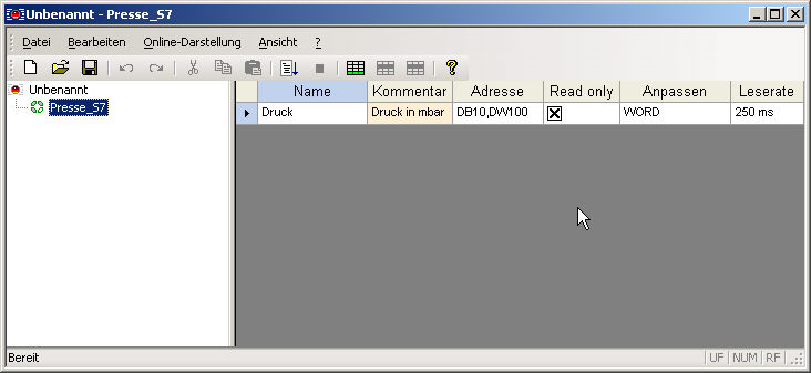
A new row is created in the right item table.
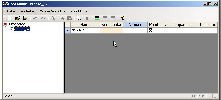
The individual table columns have the following meaning.
| Column | Importance |
|---|---|
| Name | The name of the OPC item |
| Comment | A freely available text field into which information about the item can be entered |
| Address | The symbolic address of the connection is entered in this input field. The syntax varies from control to control because the implementation of the communication drivers is very important to be as close as possible to the addressing syntax of the control manufacturers |
| Read only | Indicates whether the item should be read-only. If this option is not activated, the item can be read and written via OPC |
| To adjust | If the symbolic address of the item has been entered correctly, the foldable list field for format adaptation is filled with the possible conversion forms |
| Readings | In which time intervals the item is to be read out of the control |
Now complete the item line according to your requirements.
PLC data addressing
Operand
| Name | Abbreviation (Siemens, DE) | Abbreviation(IEC) |
|---|---|---|
| Input | E | I |
| Output | A | Q |
| Flag | M | M |
| Peripherals | P | P |
| Counter | Z | C |
| Data Block | DB | DB |
| Timer | T | 16 |
Data types
| Name | Abbreviation | Bit size | Range | Description | Array |
|---|---|---|---|---|---|
| BOOL | X | 1 | 0 to 1 | single bit representing true (1) or false (0) | x |
| BYTE | B | 8 | 0 to 255 | unsigned 8-bit | x |
| WORD | W | 16 | 0 to 65.535 | unsigned 16-bit (Word) | x |
| DWORD | D | 32 | 0 to 232 -1 | unsigned 32-bit (Double Word) | x |
| CHAR | B | 8 | A+00 to A+ff | ASCII-Code unsigned 8-bit character | x |
| INT | W | 16 | -32.768 to 32.767 | signed 16-bit integer | x |
| DINT | D | 32 | -231 to 231-1 | signed 32-bit integer (Double Word) | x |
| REAL | D | 32 | +-1.5e-45 to +-3.4e38 | IEEE754 32-bit single precision floating point number | x |
| S5TIME | W | 16 | 00.00:00:00.100 to 00.02:46:30.000 | binary coded decimal (BCD) number representing a time span | |
| TIME | D | 32 | 00.00:00:00.000 to 24.20:31:23.647 | signed 16-bit integer representing a time span in milliseconds | |
| TIME_OF_DAY | D | 32 | 00.00:00:00.000 to 00.23:59:59.999 | unsigned 16-bit integer representing a time span in milliseconds | |
| DATE | W | 16 | 01.01.1990 to 31.12.2168 | unsigned 16-bit integer representing a date in days | |
| DATE_AND_TIME | D | 64 | 00:00:00.000 01.01.1990 to 23:59:59.999 31.12.2089 | binary coded decimal (BCD) number representing a date and time | |
| S7String | B | any | A+00 to A+ff | ASCII-Code, max. 254 Bytes |
The variables are composed of operand and data type. Examples:
| Examples | Data type | Example Siemens | Example IEC |
|---|---|---|---|
| Input Byte 1, Bit 0 | BOOL | E 1.0 | I 1.0 |
| Output Byte 1, Bit 7 | BOOL | A 1.7 | Q 1.7 |
| Flag Byte 10, Bit 1 | BOOL | M 10.1 | M 10.1 |
| Data Block 1, Byte 1, Bit 0 | BOOL | DB1.DBX 1.0 | DB1.DBX 1.0 |
| Input Byte 1 | BYTE | EB 1 | IB 1 |
| Output Byte 10 | BYTE | AB 10 | QB 10 |
| Flag Byte 100 | BYTE | MB 100 | MB 100 |
| Peripherals Input Byte 0 | BYTE | PEB 0 | PIB 0 |
| Peripherals Output Byte 1 | BYTE | PAB 1 | PQB 1 |
| Data Block 1, Byte 1 | BYTE | DB1.DBB 1 | DB1.DBB 1 |
Data Block 1, Data Block 1 Typ bool, Address 1.0 → DB1.DBX 1.0
Data Block 1, Data Block Typ Byte, Address 1 → DB1.DBB 1
Peripherals Input, Typ DWORD, Address 0 → PED 0
Help:
DB#.DBB # = Data Block#.Data Block Byte #
DB#.DBW # = Data Block#.Data Block Word #
DB#.DBD # = Data Block#.Data Block Doubleword #
# = Address
The following extensions can be added to the address syntax for a data type adaptation by OPC clients that create items generically. The following are permitted as separators , or :
| Extension | Converts data type | by data type | Example |
|---|---|---|---|
| ,char | byte, 8-Bit | char, 8-Bit | MB10,char ≡ Flag byte 10 as a char data type |
| ,int | byte, 8-Bit unsigned short, 16-Bit unsigned long, 32-Bit | char, 8-Bit short, 16-Bit long, 32-Bit | MD0,int ≡ Flag word 10 as char-Data type DB10.DBW0,int ≡ Data word 0 as int-Data type DB20.DBD4,int ≡ Data double word 4 as long-Data type |
| ,float bzw. ,real | unsigned long, 32-Bit | double, according to IEEE | DB20.DBD0,real ≡ Data dooble word 0 as real-Data type |
| ,string | byte,8-bit | string, 255 byte | MB100,STRING |
| byte,8-bit | string, 40 byte | MB100[40],STRING |
Arrays are addressed with the addition [* length *].
WAGO address syntax
| Syntax | Data type | Address area |
|---|---|---|
| %In | Digital input, 1-Bit | 0 - 255 |
| %IXn | Digital input, 1-Bit | 0 - 255 |
| %IWn | Analog input, 16-Bit | 0 - 511 |
| %Qn | Digital output, 1-Bit | 0 - 255 |
| %QXn | Digital output, 1-Bit | 0 - 255 |
| %QWn | Analog output, 16-Bit | 0 - 511 |
| %RWn | Configuration register, 16-Bit | 4096 - 8191 (0x1000 - 0x1FFF) |
| %MWn | Flag, 16-Bit | 0 - 4095 |
Overview of editing symbols
| Symbol | Description |
|---|---|
 | Adds a new line at the end. Alternatively, at the end of the line, press “Enter” |
 | Adds a new line to the selected row |
 | Deletes the selected row(s) |
Overview Data type / possible formatting
Bit

Byte

Word

DWord

Array

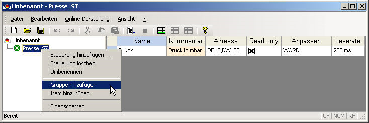
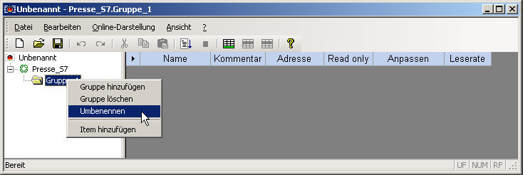
Add Group
To create a new group, click the node with the right mouse button in the left overview tree. In the pop-up menu, select the Add Group menu item.
The tree is then extended by a corresponding entry.
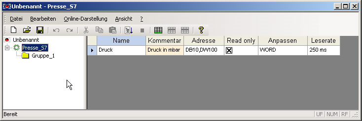
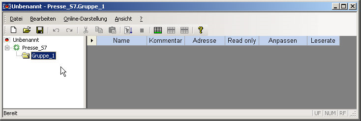
If you click on the group, the empty item table of the group is displayed.
To rename the group, right-click it and select the Rename menu item.
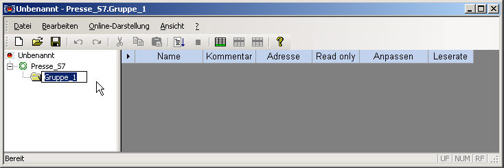
Then enter an appropriate group name.
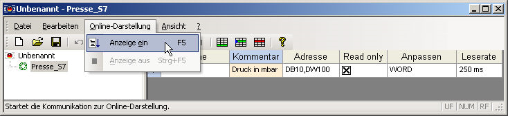
Start the online presentation
To start the online presentation, click on the  button or select the menu command Online-Display→ Display on.
In the online view, the OPCmanager automatically decouples all the configured items, that is, This also creates a maximum of communication to the control, since the OPCmanager requests all items for display.
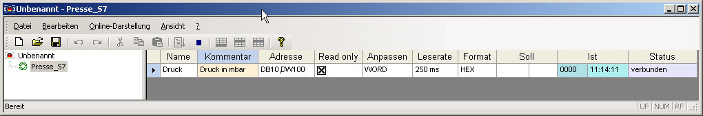
Additional table columns are displayed in the online display.
| Column | Importance |
|---|---|
| Format | Specifies the format in which the actual and target data are to be displayed. Possible forms are decimal, hexadecimal, and binary representation |
| Target | The last setpoint that was passed to the item and the time stamp when the setpoint was positively passed to the controller |
| Actual | The current actual value of the item and the corresponding time stamp when the actual value was read by the controller |
| Status | Specifies the connection status of the item for control |
To stop the online display, click on the  button or select the menu command Online-Display→ Display.
- If an OPC client is connected to the OPCmanager after it has been started as an application, the running OPCmanager application functions as an OPC server and also as a configuration surface.
- In the current OPCmanager release, you can only start the online display if the OPCmanager does not run as a stand-alone background process. The OPCmanager is only started as a background process if an OPC client with the OPCmanager as a server is active. In the task manager of the operating system, you can check whether the OPCmanager is entered in the Processes tab even though you have not started it as an application
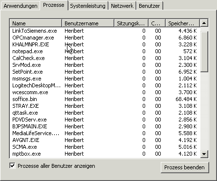
If the OPCmanager is listed as in the screenshot above, although the OPCmanager is not started as an application, it is used by an OPC client. If you first terminate the corresponding OPC client, then you can use the OPCmanager as an application for parameterization and online display.
Connect OPC-Client
- Open your OPC client
- The url to the OPCmanager is: (opcda:///OPCManager.DA.XML-DA.Server.DA/)
Now you can connect and browse the data or add variables that are not yet created and required. The data in {} is a unique ID that can be specified.
Example:
OPC Address
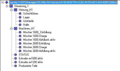
The OPC address is constructed as follows:
“Connection name”. “Node if present”. “Variables name”
For example, To read out the temperature in the shift room, enter the following address:
Control_1.Heating_H1.Schichtführer
OPC paths / files
| Path | Description |
|---|---|
| C:\ProgramData\OPCmanager | Main path of the log and ServiceFile file |
| C:\ProgramData\OPCmanager\Logfile.txt | This contains information that can be used for problem analysis. If necessary, this is to be made available to us so that problems can be solved promptly. |
| C:\ProgramData\OPCmanager\ServiceFile.txt | Contains the project to open at the start as a service. The “File→ File for service saving” must be saved by the menu item. This can be done from any user account. |
| C:\Program Files\OPCmanager | Location Application Data |
| C:\Program Files\OPCmanager\ReleaseNotes.txt | Version history |
| C:\Program Files\OPCmanager\OPCmanager.chm | help file |
OPCManager as a service
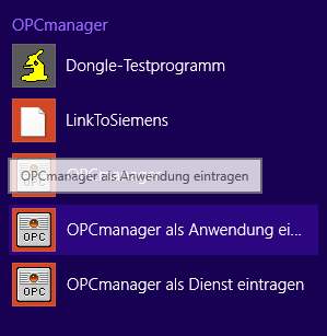
In the Start menu, here, e.g. Windows 8.1, you will find the menu item “OPCmanager as service” under “OPCmanager”.
To run, you need Admin (right click→ “Run as Admin”)
The project to be executed is defined with “File→ Save file for service”. This project applies to all user accounts defined on the system.
Cimplicity
- (E.g. With Softing OPC S7, exchange, and continue the ConnectionString
- Do not use umlauts
- Spaces and “-” are automatically replaced with “_”
- Maximum total length: 33 characters with dots!
- Browsing is performed under User Context
- When the application is started, the OPC Manager is run under Admins
- Errors during browsing may cause the OPCManager to not read data
- Install OPCManager as a service to prevent service problems
- ALt + F4 / Exit does not stop the started Cimplicity clients! (OPC Manager can not be stopped and changed)
- Note the case (connection / node / group)
Settings S7-1200/S7-1500/Logo
S7-1200/1500
The optimized block access needs to be deactivated in the data block attributes for access to the S7-1500 and S7-1200.
![]()
In the S7-1500 must be enabled in the communication setting in addition to the PUT / GET access . How this works you see here (snapshot from TIA Portal) .
![]()
LOGO!
1. Use the Logo Soft Comfort the IP address of a logo! PLCs:
![]()
2. Configure PLCs so that connections from an HMI device accepted the Logo!. To do so, go to “Tools- > Ethernet Connections” and then add a new connection.
![]()
3. Double-click on the newly created connection to access the properties.
![]()
Select:
- Server Connection
- Local TSAP: 02:00 - 02:00 decentralized TSAP
- accept all connections.
You can access DB1, inputs , outputs, flags , counters and timers with IP -S7 -LINK . Now put on “ Tools- > VM parameter map ” the variables that are to be transferred to the DB1.
![]()